CO2 Properties
The idea of utilizing CO2 to improve the recovery of oil was proposed in the 1950s when Whorton and Brownscombe received a patent for an oil-recovery method with CO2 and it has received considerable attention since then (L. Wally Holm). A lot of laboratory and deskwork has been conducted and in the 1970s, widespread field testing took place.
Under ambient conditions, carbon dioxide is a colorless, odorless, inert and noncombustible gas. Its properties under standard conditions (1.01MPa, 0 °C) are:
- Molecular weight 44.010 g/mol
- Specific gravity with respect to air 1.529
- Density 1.95 kg/m3
- Viscosity 0.0137 mPa/s
The phase behavior of pure CO2 is shown on a P-T diagram below.
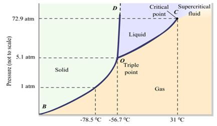
Figure 1 Carbon dioxide phase diagram
CO2 is a solid at low temperature and pressures. Solid CO2 will evaporate directly to gas at the temperature of -78.5 °C. As the temperature increases, the liquid phase appears for the first time and coexists with the solid and vapor phases at the triple point. With further increasing temperature and pressure, it reaches a critical point, where the CO2 behaves as a vapor. Its critical properties are:
Pc = 7.39 MPa (1073 psia)
Tc = 304 K (31.1°C, 37.8 °F)
Vc = 94 cm3/mol
Due to this critical temperature and pressure, CO2 behaves as a supercritical fluid under most reservoir conditions.
At the critical conditions of pressure and temperature, the viscosity of CO2 is 0.0335 cp which is higher than other probable injection gases (N2: 0.016 cp; CH4: 0.009 cp). CO2 is more soluble in oil than in the water (2 to 10 times more). Dissolving in water, CO2 increases the water viscosity and forms carbonate acid, which has a beneficial effect on shale and carbonate rocks.
CO2 Dissolution in Oil
The dissolution of CO2 in crude oil results in the main factors that contribute to enhanced oil recovery.
The solubility of CO2 in oil depends on the pressure, temperature and characteristics of the oil as was shown in figure below. ADA crude oil has a gravity of 30.3 °API while West Texas crude is of 39 °API. According to the figure, CO2 has a higher solubility in lighter oil; this value is slightly greater when the temperature is increased. When the pressure increases, solubility will increase and is sometimes limited to a saturation value.
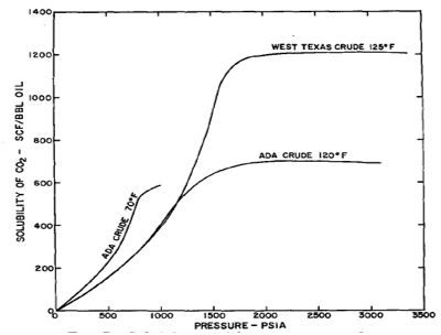
Figure 2 CO2 solubility in crude oil (Crawford et al, 1963)
- Oil Swelling
As a result of CO2 dissolution into the crude oil, the oil’s volume will increase from 10 to 60%. This phenomenon is greater for light oil and leads to lower residual oil saturation. Oil swelling increases the recovery factor on account of for a given residual oil saturation, the mass of the oil remaining in the reservoir and in standard conditions is lower than residual oil that has not contact with CO2.
- Viscosity Reduction
CO2 dissolution in crude oil also results in oil viscosity reduction. Calculations indicated that viscosity reduction was the major mechanism for EOR. Laboratory experiments show that, for any given saturation pressure, the viscosity reduction is relatively greater for higher original oil viscosity.
Miscible Displacement
The miscible state is described by L.W. Holm as: “the ability of two or more substances to form a single homogeneous phase when mix in all proportions. For petroleum reservoirs, miscibility is defined as that physical condition between two or more fluids that will permit them to mix in all proportions without the existence of an interface. If two fluid phases form after some amount of one fluid is added to others, the fluids are considered immiscible.”
There are two processes involved in a miscible gas drive; they are identified as the first contact miscibility process and the multiple contact miscibility process. First contact miscibility is achieved when both fluids are completely miscible, in all proportions without any multiple behaviors. Other solvents are not directly miscible with reservoir oil, but miscibility can be achieved under certain conditions by in-situ mass transfer between oil and solvent through repeated contacts. This kind of miscibility is called “multiple contact” or “dynamic miscibility”. When large amounts of CO2 are mixed with oil, intense mass transfers between phases occur. Multiple contact miscibility is subdivided into two processes: vaporizing gas drive and condensing gas drive. Both condensing drive and vaporizing drive are based on component transfer. Components in the injected gas and reservoir oil can be classified into 4 groups:
- Lean components: CO2, N2, and CH4 injection gas
- Light components: C1 (methane)
- Intermediate components: C2-C6, these components are present in oil but not significantly present in the injection gas
Vaporizing Gas Drive
The most important function of CO2 is that it can extract or vaporize hydrocarbons from crude oil. Vaporizing gas drive mechanism refers to a process where a lean injection gas passes over reservoir oil rich in intermediate components and extracts those fractions from the oil and concentrates at the displacement front where miscibility is achieved.
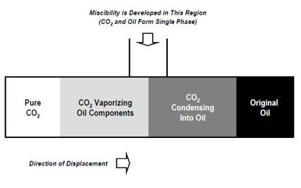
Figure 3 One dimensional schematic of CO2 miscible process (Advanced Resources International, Inc, 2005)
Condensing Gas Drive
Condensing is a process that refers to the transfer through condensation of intermediate components from rich solvent to intermediate-lean reservoir oil through condensation. In CO2 miscible flooding, the intermediates that were stripped from the oil that are present in the gas condense when the gas encounters fresh oil downstream.
Near Miscible Displacement
When the miscibility pressure cannot be reached or failed to be maintained due to either technical or economic factors, CO2 injection is evaluated as “near miscible” or “partial miscible”. It is a process between immiscible and miscible displacement. The likely mechanisms of recovery include oil swelling, viscosity reduction, and light components extraction. Normally, in such near miscible displacement cases, the ultimate oil recovery is less than the ones under miscible conditions. But on the up side, the amount of CO2 required to produce additional oil is less, making the economics of the process attractive.
Immiscible Displacement
When insufficient reservoir pressure is available or the reservoir oil composition is not favorable, injected CO2 is immiscible with reservoir oil. Even if miscibility cannot be reached, a high recovery rate still can be achieved mainly due to:
- Oil swelling as it becomes saturated with CO2
- Viscosity reduction of the swollen oil and CO2 mixture
- Solution gas drive
The first two mechanisms are the same as the miscible displacement process. The swelling of oil as CO2 goes into solution was shown to contribute to the release of trapped residual oil, especially high gravity oil. Field applications of the immiscible CO2 process, however, have been in low-gravity, high-viscosity crude oil reservoirs where the viscosity-reduction effect dominates (Holm. L.W).
Another CO2 immiscible displacement mechanism is recognized solution gas drive. Like a primary produced reservoir, after the CO2 injection process ends and the formation pressure decreases, below the pseudo-bubble point pressure, gas comes out of the solution and forms a continuous gas phase. This contributes to the oil production by providing drive energy in the form of a solution gas drive mechanism.
Minimum Miscibility Pressure
The minimum miscibility pressure (MMP) is the minimum pressure at which injection gas and reservoir oil can mix and become one phase. Above MMP, the interfacial tension between reservoir oil and injected gas disappears. Therefore, MMP is a significant parameter for screening and selecting CO2 miscible flooding candidates. Typical CO2 MMP is greater than 1,400 psia and changes under the influence of several factors.
Factors influencing MMP
Minimum miscibility pressure (MMP) is a function of temperature and oil composition. Impurities in the injected CO2 also have an impact on MMP.
- Reservoir temperature: CO2 MMP is temperature dependent which means reservoir temperature has a very significant effect on CO2 MMP determination for a given reservoir oil. Typically, MMP increases as temperature increases. A simple temperature versus bubblepoint pressure of CO2 MMP is shown below.

Figure 4 Temperature /bubblepoint pressure of CO2 MMP correlation (Yellig and Metcalfe, 1980)
- Oil characteristics: MMP between CO2 and oil increases when volatile components in oil such as C1 have a higher fraction. Intermediate components such as C2 – C4 in the reservoir fluid decreases the MMP. Moreover, higher molecular weight components such as C7+ or C5+ fraction in the reservoir oil results in higher MMP.
- Injected CO2 purity: Pure CO2 is not always available as an injection gas in the industry. Sources such as natural CO2 reservoirs and process plant waste streams always contain impurities.Another potential impure CO2 source is the produced gas from wells under CO2 flooding. Because high purity cleanup of the cycled gas is costly, produced gas is always re-injected to reduce cost. Typically, impure CO2 contains significant amounts of nitrogen, H2S, and hydrocarbons. Produced gas contains a wide variety of components from methane (CH4),
Many researchers studied the effect of impurities on MMP and provided different correlations. Yellig and Metcalfe (1980) conducted a series of slim tube experiments to measure this effect. Experimental results showed that CO2 contaminated by C1 or N2 has an adverse effect on MMP. Conversely, the addition of C2 – C4 and H2S has shown to have the effect of decreasing the MMP. Zhang P.Y and Huang.S conducted MMP experiments using rising bubble apparatus (RBA) with light oil mixed with pure or impure CO2. Results showed that, when CO2 contaminated with 10% CH4 and/or N2, MMP could increase as much as by 70%. CO2 containing 37% C3H8 could reduce the pure CO2 MMP by 45%. Effects of different contaminants on MMP are shown in the figures below. Gas compositions are listed in the table below:

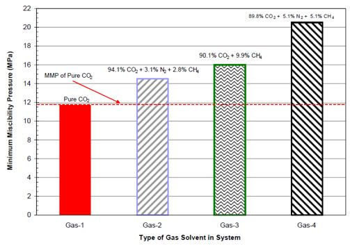
Figure 5 Effect of contaminated on MMP for steelman stock tank oil (Zhang P.Y. et al, 2004)

Figure 6 Effect of contaminated CO2 on MMP for steelman stock tank oil (Zhang P.Y. et al, 2004)
MMP Determination
In order to provide a precise MMP, different measurements have been proposed in literatures. Slim tube methods are traditionally used to estimate MMPs because they model the interaction of flow in porous media and phase behavior of crude oil. Besides slim tube methods, multi-contact mixing cell experiments can measure more accurate MMP for vaporizing or condensing gas floods. Computational methods for MMP estimation have been developed over the years based on equation of state (EOS). There are three main methods: analytical calculation using methods of characteristics, multiple cell models, and 1-D slim tube simulation.
Experimental Methods
Experimental methods include Slimtube method, rising bubble apparatus (RBA).
- Slimtube method. Slimtube method was first proposed by Yellig and Metcalfe in 1980. There was no standard method available in literature at that time for determining CO2 MMP. Slimtube method is the first satisfactory way. Over the years, slimtube method has been the most widely used laboratory technique to determine MMP for field miscible injection projects. Slimtube experiments are conducted in a long stainless steel tube and packed with certain particle-sized sand, saturated with reservoir oil at the desired test temperature and pressure. Typical diameter of the tube is 1/4 in while length ranges from 6 to 20 meters. Small tube diameter and long tube length are designed to avoid effects of CO2 fingering, transition zone length and transverse compositional variations. The coil is placed horizontally or with a very low dip angle, to reduce gravity impact on displacement. The CO2 supply cylinder is filled with 90% pure CO2 which is injected into the coil at a certain rate. A schematic of slim tube asparagus is shown in the figure below.
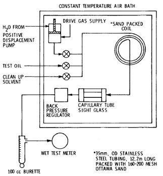
Figure 7 Schematic of slim tube experiment apparatus (Yellig and Metcalfe, 1980)
With the increase level of pressure, recovery first increases, then becomes stabilized. Recovery versus pressure is plotted after 1.2 pore volume of CO2 is injected. A typical recovery curve is given below. The breakpoint of this curve indicates displacement from immiscible to miscible. Pressure at the point is the minimum miscibility pressure.

Figure 8 Schematic of slim tube recovery plot and its corresponding MMP value (Yousef et al, 2008)
However, the length of coil, CO2 injection rate, coil diameter as well as the type and size of the packing material varies in different literatures. Orr et al (1982) pointed out that there is no unified experimental procedure or criteria defining MMP. Some of different experiment procedures in published literature for MMP determination are summarized in the table below.

In order to standardize experiment procedures, many researchers have discussed how different experiment designs affect MMP measurement. D.L. Flock and Akli Nouar (1984) studied effects of tube length and injection rate on displacement efficiency and discussed their effects on the criteria used for MMP estimation. Based on their experiments, they draw the conclusion that MMP measurement depended to a great extent on the length of the slim tube and to a lesser extent on injection rate when slim tube is long enough. The authors also concluded that a longer slim tube may result in lesser gravity and viscous fingering effects. According to the authors, a minimum requirement of coil length for a good MMP estimation is 12.2m. The authors also recommended that slim tube inner diameter should be small to minimize gravity and fingering effects.
Jamiu M. Ekundayo et al (2013) also discussed how coil length and diameter as well as injection rate influence MMP measurements. They ran 30 sets of experiments using the same oil sample and injection gas under different injection rates in two kinds of coils. 26 of the experiments were conducted in a coil with a diameter of 3.05mm having lengths of 12.2m, 18.3m and 24.4m. The other four experiments were conducted in a coil with a diameter of 4.57mm and a length of 18.3m. The authors concluded that there is no certain relationship between MMP and injection rate. High injection rate may cause deviation because true miscibility was not achieved since the gas does not have enough time to interact with the oil. Moreover, when the coil length is increased, there is a decreasing trend of MMP. MMP was also found to be lower when using a larger diameter coil while oil recoveries were found to be higher with a smaller coil.
It should be pointed out that even though the slimtube method is considered as the standard way to measure MMP, its drawbacks are that it is time consuming and expensive. It may take weeks to conduct one set of injection. Furthermore, MMP estimates may not be accurate because of dispersion and the lack of data points.
- Rising bubble technique. Rising bubble apparatus was designed as a reliable and fast alternative to a slim tube measurement. It was first proposed by Christiansen and Haines in 1987. Unlike the slimtube measurement, MMP determination is not based on oil recovery and its corresponding pressure. Rising bubble measurement is based on a direct visual observation. Rising bubble apparatus consists of a flat glass tube installed vertically in a high-pressure sight gauge. The whole apparatus is placed in a temperature-controlled bath. The tube is flat with a vertical incident light so that gas bubbles are visible even in opaque crude oil. Visible portion of the tube is about 20cm long, and internal cross sectional area of the glass tube is 1x5mm. Gas bubbles are injected into the glass tube from a hollow needle at the bottom of the sight gauge. The sight gauge and glass tube are initially filled with distilled water. Then oil is injected into the glass from the top of the tube to displace water. The bottom portion of glass tube is still filled with water while the remainder of tube is filled with oil. A small bubble of gas is injected into the tube from bottom of tube and then it rises through the whole water/oil column. After two or three gas bubbles have been injected through the oil, the oil will be replaced with fresh oil. The whole rising process of the bubble and its shape and behavior are observed and photographed with a camera. The author divided bubble behavior into three types according to pressures. Type A is below the MMP: the bubble will remain in its initial shape while rising through the column of oil, however the size of the bubble will shrink. Type B is at or slightly above MMP: the gas/oil interface will vanish from the bottom of bubble and then the contents of it rapidly disperse in the oil. This is a multiple contact miscibility process. Type C is above the MMP: the bubble will disperse faster than type B. This is a first contact miscibility. Unlike the slim tube method, it takes between 5 to 30 seconds for a bubble to rise through oil column with RBA. The whole MMP measurement experiment takes about 1-2 hours while it takes weeks using the slimtube method.
- Numerical Methods. An experimental method such as the slimtube estimation is subjected to the impact of experimental parameters and multiphase flow parameters such as relative permeability. The rising bubble and VIT do not completely model multi-contact mechanisms between gas and oil. Because of the drawbacks of experiments, computational methods have been developed over the years.
- Multiple cell model. The multiple cell model concept is based on running a series of repeated forward and reverse contact experiments, resulting in new initial oil and initial gas compositions. As was described in the previous section, miscible displacement consists of condensing and vaporizing gas drives. Miscibility in vaporizing drives is developed at the leading edge of the displacement while for condensing drives, it is developed at the trailing edge of the development. For pure condensing or vaporizing drive, multiple cell model could provide robust and reliable estimations, however, for combined CV drives which most displacements, are multiple cell model methods are not considered convincing.
- 1-D slimtube simulation. One dimensional the slimtube simulation is a favorable alternative of slim tube experiment as the latter is expensive and time consuming. The simulation utilizes well-characterized EOS fluid models to mimic the flow in porous media. It is based on compositional simulation of solvent injection into one dimensional porous media under miscible conditions. A prerequisite for the simulation is that the numerical and physical diffusion of the fluid have to match. So welling test must be completed on the reservoir fluid before simulation.
- Empirical correlations. Empirical correlations predict CO2 MMP as a function of three variables: mole fractions of light components in the reservoir oil, molecular weight of a plus fraction, and temperature. Holm and Josendal (1974) proposed the first MMP correlation based on reservoir temperature and molecular weight of C5+ components in reservoir oil. A correlation was provided by National Petroleum Council (NPC) in 1976, predicting MMP according to temperature and oil gravity. Yelling and Metcalfe (1980) simplified the correlation so that MMP could be predicted based on reservoir temperature. Alston et al (1985) proposed a correlation with temperature, oil composition and an averaged weight critical temperature for impure CO2. Factors such as extrapolated vapor pressure of CO2 were considered by some other researchers.
- Method of characteristics. Method of characteristic (MOC) aims to solve the problem of multi-component fluid flow in porous media. This method enables the construction of an analytical solution describing the composition path from initial gas composition to the initial oil composition. MOC is associated to key tie-line approach. Earliest attempts to calculate MMPs referring to key lines were ternary theory for multi-contact miscible displacement. MMP is defined as the pressure at which the critical tie line passes exactly through the gas representative point. Wang and Orr (1997) developed a four-composition system as shown in the figure below. Three key types of tie-lines control miscibility in a multi-component system. MMP is determined as the lowest pressure when the length of one of the key tie-lines becomes 0.

Figure 9 Key tie-lines intersect each other for a displacement of oil O by gas G (Wang and Orr, 1997)
CO2 Injection for Mobility Control
- CO2 Injection Problems: Gas injection has many advantages over water flooding especially in tight reservoirs. Low permeability and porosity will decrease injectivity and feasibility for water flooding. However, there are some problems associated with gas injection. One of the major problems associated with CO2 flooding in particular is its low viscosity, resulting in unfavorable mobility difference between CO2 and oil mobility. With high mobility, CO2 bypasses most of the crude oil in the flood pattern and, seeks the path of least resistance through the largest throats or pores and takes the most direct route between the injection well and the production well. Sometimes, due to reservoir heterogeneity, CO2 goes through high permeable layers and fractures. As a consequence, much of the oil is not contacted and left unswept. Indications of poor sweep efficiency is seen by early CO2 breakthrough. These disadvantages are known as fingering and channeling problems. In addition, gravity overriding problem is unfavorable due to the low gravity of CO2. Therefore, mobility control is a significant problem during CO2 flooding. Several methods to alleviate the situation have been investigated:
- Alternate injection of water with CO2
- Installations of packers that isolate the high permeable zone
- Co-injected with surfactant foam and alternate with water
- Inject gel to target zone
- Water Alternating Gas Injection: Alternative injection of water with CO2 is the most widely used mobility control method. The first field application of WAG dated back to 1957, it was implemented by Mobil on the North Pembina Field in Alberta, Canada. Since then, WAG has been implemented successfully in a number of fields around the world. CO2 miscible displacement has excellent microscopic sweep efficiency and water flooding is less subject to gravity segregation and frontal stabilities. The combination of water flooding with CO2 flooding can provide better macroscopic and microscopic displacement efficiency. Technically, CO2 and water are injected alternatively into the wellbore under certain slug size and ratio. Sometimes a big slug of CO2 is injected previously before WAG for a quick response and higher recovery. In the field, WAG injection is sub-classified as constant WAG, simultaneous WAG, and tapered WAG (TWAG) injection. Different WAG ratios and slug sizes are designed under different reservoir conditions.
- Foam Assisted WAG Injection: Foam assisted WAG (FAWAG) is also called surfactant alternating gas injection (SAG). Foam is generated when gas passes through surfactant in an aqueous phase and generates stable dispersion of gas bubbles. Foam has a higher apparent viscosity and lower mobility with a formation. As a result, SAG is considered to have a better effect than WAG on mitigating the problems of frontal instability as well as the fingering problems in heterogeneous reservoir which otherwise induces the early breakthrough of CO2. A figure visualizes the comparison among continuous CO2 injection, WAG injection, and SAG as shown below. Since surfactant is involved, salinity, pH, and surfactant concentration have to be taken into consideration when designing a surfactant and WAG co-injection.

Figure 10 Comparison of different CO2 injection strategies (http://www.eor-alliance.com/solutions/foam/)
- Gel Injection: Gel treatment is considered the most aggressive conformance control method. Without significantly damaging hydrocarbon productivity, gel acts as a blocking agent and reduces channeling through fractures or high permeable zones. Several gel treatments in CO2 floods were reported in literature. Projects such as the Wertz Field experienced a significant recovery and conformance improvement after gel treatment.
Other CO2 Flooding Problems
- Asphaltene Deposition and Scale: When mixed with crude oil, CO2 has significant potential for flocculating the asphaltene molecules in the oil. This phenomenon may happen in the near injection well bore area where CO2 content of the mixture is as high as 60-70% (Honarpour et al, 2010). Normally, when oil is stabilized by resins and intermediate hydrocarbon components, asphaltene exists as a dispersed phase within the oil. During the vaporizing drives, as CO2 extracts intermediate components from oil, it leads to instability. As a result, asphaltene will flocculate and eventually precipitate. Asphaltene may cause near wellbore pore throats to plug and thus affect permeability and even CO2 injectivity.
- Formation Dissolution: As an acid gas when dissolved in water, CO2 forms a weak acid which in turn can react with formation, especially in carbonates. Reaction between CO2-formed acid and the formation can cause rock dissolution and changes to the reservoir heterogeneity.